Introduction
My goal with this article was to document my derivation of the OpenGL perspective projection matrix from scratch to make sure I understand how and why it works and share it with the hope that someone may found some part of this document useful.
The equations and everything else are based on my understanding, so please double-check if you use anything from the article.
How 3D points can be displayed on 2D surface
It all boils down to the fact that objects farther look smaller.
Although in this article we'll be focusing only on the perspective projection matrix, a 3D scene point goes through the following key phases when transforming it into 2D space:
- Multiplication with the Perspective Projection Matrix: Converts 3D points into clip coordinates.
- Clipping: Removes portions of the scene not visible in the view frustum.
- Perspective Division: Converts clip coordinates into normalized device coordinates (NDC) by dividing by the w-component.
- Mapping to Screen Coordinates: The NDCs are mapped to screen coordinates for rendering.
Viewing frustum
The viewing frustum is a pyramid that shows the portion of 3D space that is visible in the rendered scene. The center of the frustum represents the viewer's position or camera location.
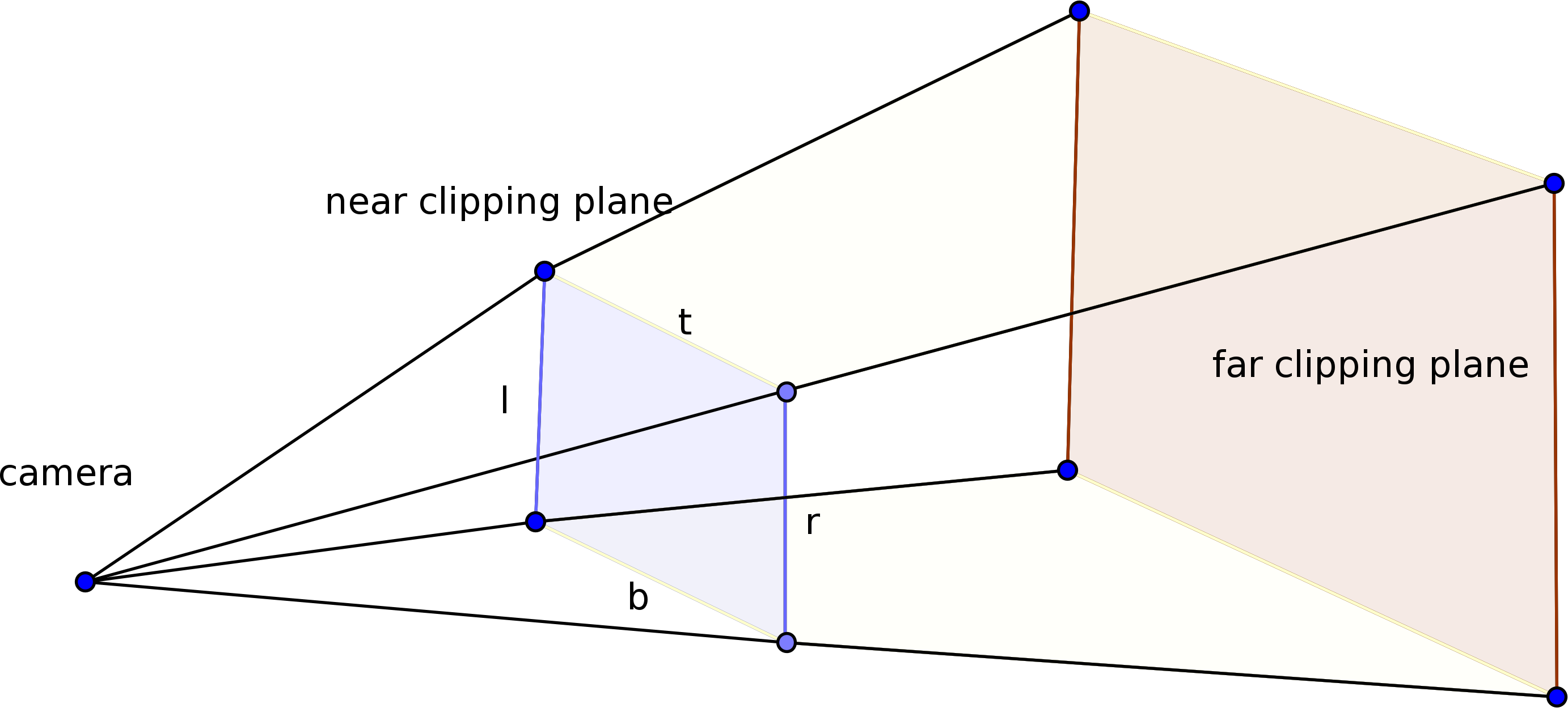
The frustum contains 6 planes:
- Far clipping plane: Objects beyond the far clipping pane are not visible.
- Near clipping plane: Objects behind the near clipping pane are not visible. Also, the 2D image corresponds to the projection of the 3D points onto the near clipping plane, as seen from the camera's perspective, see in the next paragraph.
- Left plane: acts as the left boundary of the frustum
- Right plane: acts as the right boundary of the frustum
- Top plane
- Bottom plane
Let's look at the following image:
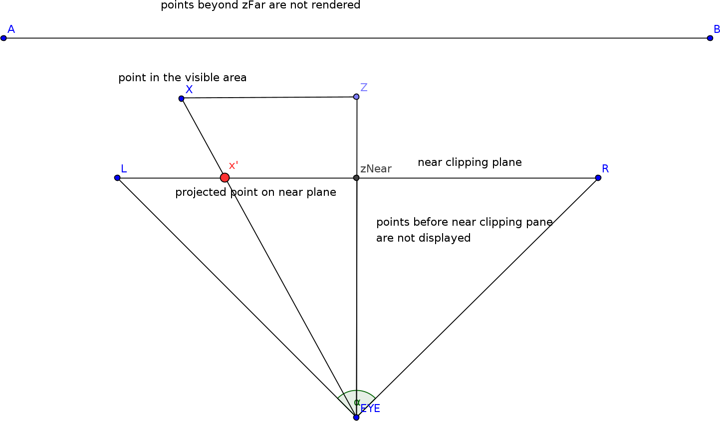
This figure shows a horizontal slice of the viewing frustum. If we project a ray from the eye (camera) towards the 3D point then the rays passes through each pixel on the near clipping plane and extend into the scene. Where these rays intersect determines what is seen at each pixel on the 2D screen. The collection of these intersecting points, translated onto the near clipping plane builds up the 2D image.
Perspective projection matrix
Since the screen is a 2 dimensional surface we need a method that projects the 3D objects onto the screen.
That is, that we need technique that maps an arbitrary 3D (X, Y, Z) point to 2D (x, z) that can be that can be rendered on the screen. That's where the perspective projection matrix helps us.

The 3D points are multiplied by the perspective projection matrix, resulting in what are known as clip coordinates.
An important aspect of this transformation is the introduction of an additional component called w. This component is a result of using homogeneous coordinates. Homogeneous coordinates means adding an extra dimension to the traditional (x,y,z) coordinates, resulting in a four-component system (x,y,z,w).
There are many reasons why the fourth component, thus 4x4 matrices are needed, just a few of them:
- Later in this article we'll create the formula for mapping the Z coordinate into the range of [-1, 1]. Without the fourth component, it would not be possible to encode the formula into a 3x3 perspective projection matrix.
- Graphics hardware and APIs (like OpenGL and DirectX) are optimized for operations on 4x4 matrices.
The clip coordinates represent an intermediate stage in the rendering process and cannot be directly drawn onto the screen. First, clipping is performed on these coordinates to remove parts of the scene that are outside the view frustum.
Once the clipping is done, a perspective division is applied, where each clip coordinate is divided by its own w-component (the fourth component of the clip coordinates). This step transforms the clip coordinates into normalized device coordinates (NDC), which can then be mapped to screen coordinates. Finally, these screen coordinates are used to render the points onto the 2D screen.
The usual value of w in the 3D scene points is 1. The perspective projection matrix is set up in a way that the resulting z component in the clip coordinates will be -Z of the 3D scene point.
Why -Z? According to OpenGL convention the visible area has negative Z value in 3D space. But then if the perspective division happens with a negative Z value, then it would invert the coordinates, effectively mirroring the image horizontally and vertically. So one reason we chose w = -Z is to preserve the coordinate orientation.
Derivation
The x and y values
Our goal is to create a projection matrix that'll transform the x, y and z coordinates in a way that after the perspective division with w they will be in the [-1, 1] range if they are visible.
First, let's derive the x coordinate in the clip space. Let's note it with x'. This is easy by leveraging the similar triangles:


We already know that the Z coordinate is negative if it's in front of the camera. On the other hand, the zNear and zFar are positive values. It's an OpenGL convention. Using this information we can rewrite the formula as follows:

Now we map the x' on the [l, r] range:

We assume l will be negative value and r will be positive. This formula gives us a value in the [0, 1] range. However, we want a value in the [-1, 1] range instead.
Creating such a mapping function is fairly easy:

We need to multiply our previous formula by A and then add the constant B to it.
If we substutie the values then we can get the following equations. px will be the 2D coordinate that can be drawn onto the screen.
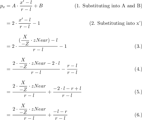
In the 6th step we finally have the formula that maps the X coordinate of a 3D scene point into the [-1, 1] NDC range that can be drawn onto the screen.
We need to build this formula into our projection matrix. We can't put this value directly into our perspective projecti matrix because remember that the perspective projection matrix does not perform the w division, that'll be a step later.
The final point can be defined as follows:

And we have to find the values for a11, a12, a13 and a14.
To express this formula in matrix terms, we assign a11 as the coefficient that will multiply the X value. The perspective division by −Z is not included in the matrix, since it is part of the homogeneous coordinate transformation that occurs afterward.
Now we have to encode the right operand of the formula into the matrix, that's a bit more tricky. We know that there will be a w division later which would modify this operand.
To neutralize the division with w we should put it into a13 because of the multiplication of Z from the 3D screen points. However, we multiply with positive Z but divide with w (which is negative Z). To balance out this effect we need to multiply the dividend by -1:

The z value
Now let's see derive the formula for the the z component. That is, we're looking for a formula that maps the z coordinate from 3D screen space into the [-1, 1] range of NDC space. This is essential to clip everything before and beyond the near and far clipping planes.
We know that if Z equals to zNear then it's on the near clipping plane. On the other hand, if Z equals to zFar then it's on the far clipping plane:
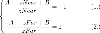
Let's solve it for B:

Substutue and solve it for A:
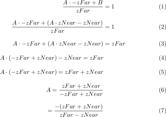
Substutie in for B:
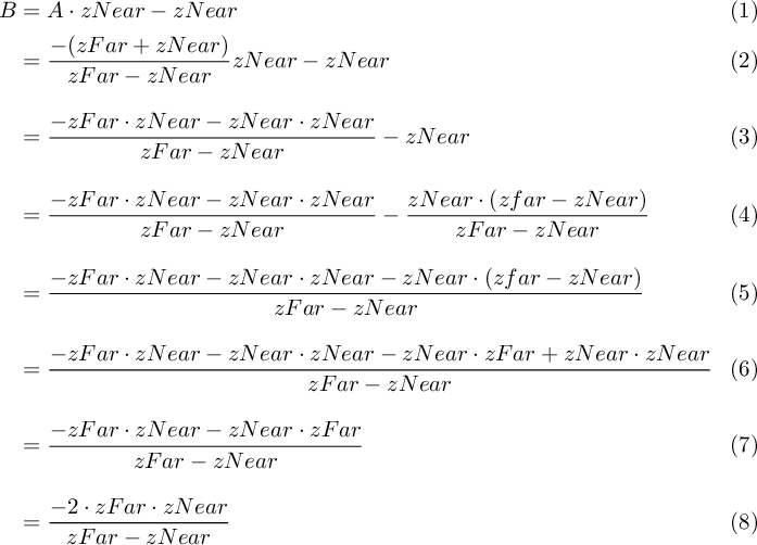
If we substitute everything we derived so far we'll get the OpenGL perspective projection matrix:
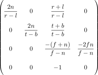
Picking values for the frustum
Now that we have built up the perspective projection matrix we need to assign values to the left, right, top, bottom, zNear and zFar parameters.
For simplicity purposes let's assume that the right half of the screen is symmetrical to the left half so is the top half to the bottom half.
We can easily find the value for the right parameter using some trigonometry (see the frustum image above). We just have to define the field of view (FOV).
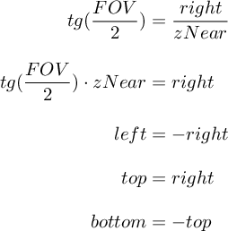
Setting a value for zNear and zFar is arbittrary, a common choice is 0.1 for zNear and 100.0 for zFar.
Conclusion
In this article we have derived the OpenGL perspective projection matrix from the ground.